
Immersion Mining Enclosure Installation

Immersion Mining Rack System Installation

Immersion Optimized DryCooler Installation

Installation & commissioning of the Immersion Mining Enclosure & ICP40 Dry Cooler

A. Preparation for the installation of immersion cooling system.

1. See the manuals and tutorials: The most important thing you should do before the installation, is to familiarize yourselves with manuals. Please take your time and read or see all below information which will result with successful installation:

Please go through this material and if you find some issue during the installation we are available to support you directly – please contact them every time if you are stuck on some step or you have some questions which we didn’t cover here. We work in GMT+2 / CET time, but we respond also outside business hours.

2. Get help if needed: If you’re not feeling comfortable with DIY handwork, just focus on mining and hire a contractor for the installation – especially for the more complex rack installation. Send them link for the manuals and any plumber / HVAC installer should manage to install the system, even though immersion systems are quite new for everybody.

3. Have tools and accessories ready: Prepare all the tools and accessories which may be helpful for the installation

  • paper towels: get lots of them. They are always helpful, especially at later stage when you work with dielectric fluid
  • usual tools: pliers, wrench or monkey wrench, Allen key No.10, hex socket wrench number 10,
  • cutting tools: sharp utility knife or flexible pipe cutter or PVC pipe cutter.
  • transformer: you will need that to operate our systems. We need just 110/120V connection but with transformer like such: https://www.amazon.com/Yinleader-Voltage-Transformer-Converter-120Volt/dp/B07PPZLX5K
  • demineralized water – for the primary loop (between dry cooler and enclosure). We do not transport water you can source demineralized or distilled or treated water anywhere.
  • anti corrosion /antifreeze additive (if needed): if you live in colder climate and expect freezing temperatures during winter – buy additional glycol or antifreeze for the loop between dry cooler and DCX Immersion Mining Enclosure
  • drill pump (optionally): if you prepare for the rack system installation – small drill pump with tubing will help to fill the whole primary loop faster
  • time – the most important tool: take your time, plan the startup of the system, plan the time to release the air, plan when to immerse the miners into the Immersion Mining Enclosure.

4. Take your time: do not expect to finish everything within 2 hours. Do not start on Friday evening – make sure you have enough time to position and connect the components, filling the loop, or venting the loop (time-consuming), configuring the enclosure, preparing your miners etc. If you want us to be available for remote support, please contact us in advance, as we normally do not provide direct support on Sunday evening. Plan all the steps in advance and have time to execute.

B. Delivery, collection and acceptance of the Immersion Cooling System shipment.

1. Prepare for pickup and unloading: Your Immersion Mining Enclosure + ICP40 Dry Cooler kit will be shipped on a single euro pallet (120×80). Please take into account that our systems are pretty big and heavy. Depending on delivery location and current services offered by forwarders, it may require special delivery or additional work for safe unloading. Single Enclosure bundles are shipped on one euro pallet and may weigh from up to 400kg / 800 lbs – depending on options. You will need 1-2 people to unload the system safely.

Single Rack system requires a long custom pallet with weight of up to 1200 kg /2600 lbs. You will need 3-4 people to unload the system safely and if possible – you can unpack goods on the truck and remove the system bit by bit.We would appreciate your confirmation of upon receiving those goods. Please make sure you are prepared for pickup, having enough time and people to perform safe unloading.

2. Make photo / video documentation of the package: After receiving the package, inspect it and photo / video document any scratches or dent’s. Make sure any issues will be documented in the shipment documents. Remove packaging wrap carefully, do not cut the tubing or damage any components of the system. Also, please document carefully delivered package with photos or videos before unwraping and after that. If possible, do that in the presence of the driver. All our packages are insured to the full value, so please make a claim for any noticed issue.

C. Installation of the Immersion Mining Enclosure / ICP40 Dry Cooler

1. Your Immersion Mining Enclosure + ICP40 Dry Cooler kit will be shipped on a single euro pallet (120×80). It contains all the components necessary to set everything up. Most of the elements and accessories are hidden inside the immersion tank and the dry loop filling pump package. 

Immersion Mining Enclosure and ICP40 bundle consists of :

  • immersion enclosure with circulation pump and heat exchanger
  • enclosure cover
  • flow deflector grid
  • flow director plate (universal or custom for specific miner configuration
  • 10 x 25L container with ThermaSafe R™ engineered dielectric fluid
  • 10L container with solvent
  • orange pressure pump
  • dcx monitor – temperature sensor
  • anti corrosion /antifreeze additive
  • 20m (65ft) of industrial hot water / steam tubing
  • 4 gbs clamps to secure the tubing connction
  • (optional) PDU or modular switchgear box
  • (optional) dcx fan emulators

3. Take the ICP40 dry cooler off the pallet and put it down horizontally on its rubber anti-vibration feet. New ICP40 models are bigger, so feet won’t fit on the pallet. If the device doesn’t have feet mounted, make sure to attach them before placing the equipment on the ground using the provided set of screws. Remove the Immersion Mining Enclosure and other components of the package and find a secure place to operate inside your facility.

4. Dry cooler must be installed outside with the access to the fresh air. Place the dry cooler outside your facility, preferably on a northern wall of the building. Keep at least 16-20″ (40-50 cm) distance between the device and the wall. We suggest 40″ (100 cm) in the back and front of the dry cooler. Provided tubing (20 m roll) allows positioning ICP40 dry cooler 10 m (32′) away from the Immersion Mining Enclosure.

5. Immersion Mining Enclosure must be located inside the building, in the safe / stable area which will support the weight of the enclosure, miners and the fluid which can take up to 300 kg (600lbs). You can buy a spill containment pallet or plastic foil to protect the area from any spill or dielectric fluid dripping from any of the components. You can use pallet and leave the enclosure on it. Enclosure should be kept away from children and animals and closed with the lid.

6. Find a 20 m (63ft)  long rubber hose in the package, cut it by half and attach it to saw-shaped hose fittings, pushing it all the way down to the very end of the fitting. Use gbs clamps to fasten the hose at the very base of the fitting, not further than 2 mm from the fitting nut. Caution: ends of the rubber hose must be cut clean and straight, without spikes or bumps.

7. Establish a pipe connection between the immersion enclosure and the dry cooler without bending piping too much, so that no flow restrictions take place. Both components may be installed on different levels (e.g. the tank stays in the cellar and the dry cooler is on the ground). Due to the integrated air vent in the dry cooler, the top part of the dry cooler should be set up higher than the upper lid of the enclosure, or you will have to install the air vent in the highest point of the installation.

Make sure tubing is connected the right way: Dry Cooler’s inlet (supply from enclosure) is under the pump, outlet (return) is on the dry cooler corner – right side of the pump compartment. The immersion mining enclosure’s inlet (supply from dry cooler) is on the bottom of the heat exchanger (bottom fitting), the outlet (return to the dry cooler) is just above it (top fitting). If you run your connection through the opening in the wall, mark one of the tubes on both sides to avoid the mismatch.

8. Besides maintenance works, especially when the system is fully loaded and operational, the pump compartment must be completely closed. Otherwise, fans would suck air through the pump compartment, instead of the dry cooler’s fin pack, as it’s supposed to be. 

D. Hydraulic commissioning

1. On the right side of the dry cooler you will find a pump / fan controller compartment. Remove black plastic caps which cover the screws that hold a cover of the pump compartment. Remove the screws and take off a side panel. Removing the panel might require a little effort, so grab a black handle tight and take the lid off.

Pump compartment consists of:

  • circulation pump
  • switchgear with two fuses (W for fans and P for pump)
  • adaptive fan controller
  • controller temperature sensor
  • one-way valve for loop filling
  • vent valve
  • ball valve for maintenance works
  • in – and outflow collector

2. Unpack an orange dry cooler loop filling hand pump, take everything out from the inside and attach the removable lever. The pump has 2 valves: V1 (closer to the manometer), V2 (further away from it) and the manometer itself. The red arrow of the manometer shows maximum instantaneous pressure in the system, and it should be reset before filling manually (turn the screw in the middle to the left). Manometer has a scale in mPa, psi and bar measurement units. A black outer scale of the manometer shows pressure in BAR.

3. In order to prepare the system for work:

  • Attach the hand pump hose to the one-way valve using provided nipple
  • Mount the lever handle
  • Fill the pump container with either demineralized or distilled water. Do not pump dielectric fluid into the loop between dry cooler and enclosure. Dielectric fluid goes only into the enclosure. About 25 liters of fluid are needed to fill the loop of the ICP40. In case of spilling the fluid or refills – please make sure you have from 30 to 40L. If you expect negative temperatures (below 0 C / 32 F) please prepare a correct mixture of demineralized water and antifreeze, glycol fluid.

4. The kit includes a Febi fluid concentrate with special additives for cooling systems. Pour half of this bottle into demineralized water. This will protect your dry cooler from the corrosion and deposits, but in order to provide adequate freeze protection for any system, the glycol-water solution must maintain a freezing point at least 5°F (3°C) below the lowest expected ambient temperature.

By definition, freeze point is the temperature where ice crystals begin to form. The fluid will become slushy, but it will not expand. Burst protection accounts for temperatures that fall well below the lowest anticipated ambient temperature and ice crystals begin to form. The burst point of a fluid is the temperature where the fluid will freeze solid, expand, and break pipes or damage other parts of the equipment. Below table presents the correct mixture ratio which is required for protection of the system. Again If you expect negative temperatures (below 0 C / 32 F) please prepare a correct mixture of demineralized water and antifreeze, glycol fluid otherwise you risk damaging your equipment beyond the repair.

5. Unscrew the cap of the one-way valve, and screw the nipple in (you will find on the hose of the loop filling hand pump).

6. Red arrow of the manometer shows maximum instantaneous pressure in the system. While releasing the pressure, remember about resetting the red arrow’s position by turning it to the left. After setting it to zero, the whole setup must be filled with operational pressure of up to 6 bar. A black outer scale of the manometer shows pressure in BAR.

Before filling the loop, open the valve above the dry cooler pump (red handle on the pipe). Fill the pump with water or water / glycol mixture and start pumping the fluid into the dry cooler. There are two valves and a pressure gauge on the pressure pump. In order to fill the loop, open V1 (close to manometer)  counterclockwise and close V2 clockwise.

7. After filling the System to a maximum of 10 bar, briefly open the vent valve at the top and release air. When pumping up the system, you will have to remove excessive air from the system multiple times.

8. Venting the system: ICP40 has a vent in the upper part of the dry cooler, located just above the pump. Use it to vent the system. In order to do that, you’re going to need to:

  • Turn the valve counterclockwise for a while to release excessive air from the loop. A small amount of water may also sprinkle out during this operation, but this is totally normal. This action may  be repeated many times during the setup and launch of the loop.
  • After filling the loop (Dry Cooler – Enclosure) turn the pump on. It can be done by lifting the P fuse in the dry cooler switchboard. Run the pump without the fans (W) to hear the hydraulics work and vent the system properly.
  • To release air from the dry cooler’s recesses, you can shake and tilt the device several times.
  • After a long while, you’re going to have to vent the system again by briefly opening the vent valve.
  • After launching miners and warming up circulation, venting will have to be done over. When the pump is running smoothly and you can’t hear any air bubbles in the system, you may consider the loop to be properly vented.

9. Electrical connection: connect the dry cooler and the enclosure to power supply. All our enclosure components use single phase 230V (220-240V range), 50/60Hz power connection. Warning – do not confuse single phase 220-240V range, with so-called American 240V / split phase or dual phase 240V standard. This connection with 2 hot legs with 110-120V results with 243-244V and will eventually damage your equipment, including fan controller and capacitors in the fans. To avoid that just buy voltage converter that will convert USA 110V to desired EU/ ASIA 230 VAC. For continuous use, you’ll need conversion with at least double capacity than the connected component power, so everything from 2500W range is fine.

Again: It will not work properly with mentioned US 240V, it will not work with 208V either. Just buy the transformer, connect two plugs (from ICP40 and Immersion Enclosure) to the transformer – problem solved. Example transformer: https://www.amazon.com/Yinleader-Voltage-Transformer-Converter-120Volt/dp/B07PPZLX5K)

Power supply and power consumption of the devices:

  • Circulation pump on the enclosure – (260W)
  • Circulation pumps and fans in ICP40 Dry cooler Pump – 180W max. Fans 2x 380W / 1.75A max = 940W per ICP40 maximum).
  • In total 40kW Immersion Enclosure system will utilize = 1.12 kW total (approx. since dry cooler pump and fans are adaptive) which is exactly how much you’ll save removing fans from 8 x s19 miner.

E. Configuration of the DCX Immersion Enclosure

1. DCX Immersion Enclosure capacity: The enclosure is sized in terms of performance and mechanically to cool a relatively small pool of a tightly packed group of ASIC miners or GPUs. We designed the system this way to avoid issues with long tanks, uneven flow and overheating of individual miners. The enclosure is designed to cool most popular miner form factors:

  • S19/S19PRo/XP Antminer form factor – 8 miners per enclosure 
  • M30/M31/M50 Whatsminer form factor – 12-13 miners per enclosure
  • GPU Cards – from 56 to 65 cards depending on the mainboard, PSU and other components dimensions.
  • 19-inch server sized miners – utilizing sleds or brackets to install server components

2. Grid and Flow Plate configuration: DCX Immersion Enclosure is equipped with grid and flow plates. Grid is a mandatory component required for the proper operation of the enclosure and flow plates are optional, but a very effective add-on. We provide universal flow plates or dedicated for the specific miner type.

V Grid: the grid should be placed on the bottom of the enclosure in the way that V shaped elements are pointing to the back of the enclosure as presented with black V’s on the drawing. Grid elevates the miners and allows fluid to fully saturate the devices with needed flow to cool the systems properly. 

Flow Plates: It is very important to constrain the flow inside the enclosure, so it circulates only through the miners and not around them. In case of ASIC miners you should use provided flow plates which direct the fluid to the ASIC hashboards. Plates should be placed directly on top of the grid. The plates have pre-cut openings – before placing miners on top of the plates, you should open the areas where miners are installed and leave openings closed if the miner is not present. You can remove the covers from the openings manually twisting the cover until it can be removed. Then please place the flow plates on the grid in a chosen pattern. An example setting for the S19 Antminer dedicated Flow Plates can be seen below on the drawing.

3. Dielectric Fluid level: It is very important to properly set the fluid level in the DCX Immersion Enclosure. Depending on the amount of miners there may be to low or to high fluid level. Known symptoms of that situation are:

  • sucking the air through the outlet: results in sucking sound and white / cloudy appearance of the fluid. The air is mixed into the dielectric fluid. The fluid will eventually become clear again with air bubbles evacuated from the fluid when you will add fluid to the correct level.
  • overheating – either to low or to high fluid level will result in incorrect fluid flow.

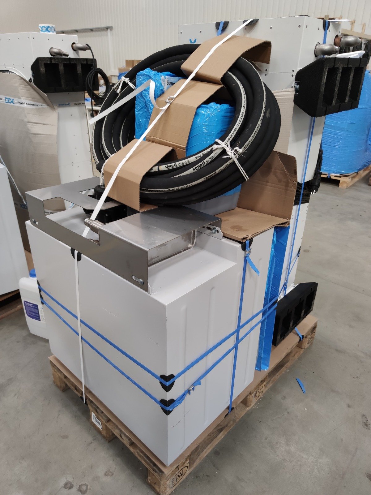
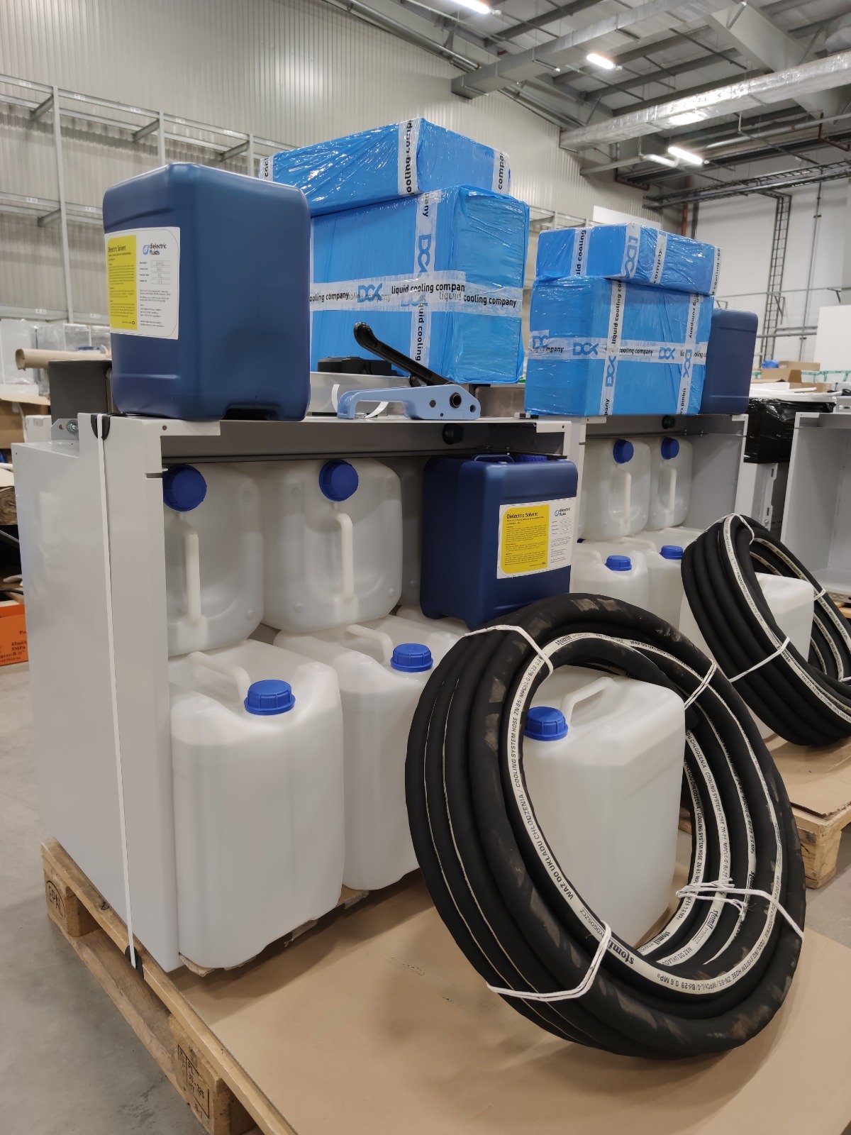
We provide 10 pcs of 22L containers = 220L total with every DCX Immersion Mining Enclosure. It is enough to operate with 8 x s19 miners or 12 Whatsminers, however it may be not enough if you plan to immerse just one miner for testing. In that case you can use the provided container filled with sand or water – anything that make the container heavier than the weight of the fluid it displaces. If using water as a weight, please make sure the container is completely dry when placed inside the dielectric fluid (including top of the container, handle etc.). Also make sure it’s firmly closed and that the container cap is located above the fluid level.

To achieve effective cooling with a proper temperature stratification of the fluid, you should make sure the fluid level is just slightly higher than the top edge of the black divider which separates the miner compartment from the fluid recovery channel. Fluid should barely overflow the divider, creating a waterfall effect in the fluid recovery channel. If you use lower miners (example S17 / S15) you can remove part of the divider lowering the needed fluid level. The correct fluid amount shown on the drawing below.

4. S19 Antminer or similar configuration: If grid, flow plates and fluid level are configured properly DCX Immersion Enclosure will provide effective heat transfer with a DeltaT of 20 to 25C. The miners should be placed vertically on the top of the grid and flow plates, with flow plates openings removed. Miners can be positioned with power sockets facing top or bottom of the enclosure. For the best cooling effect we recommend miners located in the way that hashboards are located closer to the middle of the enclosure having part of the miners flipped and part non flipped. If you plan to operate with a limited amount of miners you should place first miners in the front of the enclosure starting from the middle.

5. GPU bracket configuration: We offer 2 types of GPU card brackets:

  • 2×4 –  in total 8 brackets per enclosure. Each bracket holds up to 7 GPUs, depending on the GPU build, heatsink build, mainboard dimensions, PSU amount and dimensions. In total this kit will hold 56 GPU cards with power supplies. Dedicated to the ATX boards with GPUs using PCI risers.
  • 1×5 –  in total 5 brackets per enclosure. Each bracket holds up to13 GPUs, depending on the GPU build, heatsink build, mainboard dimensions, PSU amount and dimensions. In total this kit will hold 65 GPU cards with power supplies. This is the most universal bracket, will fit every mainboard and GPU model.

Brackets can also be used to install different 19-inch server sized miners or servers. Proper position of the brackets in the enclosure shown on the drawings below:

F. Adaptive Fan controller settings

1. ICP40 fan operating modes: ICP40’s fans can work in constant mode – at 100% speed, or in adaptive mode – in this case their speed is controlled by a special controller:

  • In the constant mode, turn on the fan (fuse W up), but the speed controller should be turned off (position 0) at the same time.
  • In adaptive mode, the controller should be turned to position 1, and the W fuse should be down. In this case fan speed depends on the temperature of the fluid flowing out of the dry cooler, which is measured by a sensor mounted on the return manifold.

2. Programming feature of the ICP40 Adaptive Fan Controller: Once being switched on, the controller starts working in auto mode. When the heat sensor detects an excess of switch- on temperature threshold, fans start working at minimum speed. Fan speed grows linearly according to heat increase, until they reach maximum speed activation temperature. Fans keep working at max speed when heat exceeds that level. You may want to adjust the speed of the fans and make it faster during the moderately cold season to avoid buzzing of the fans on the automatically set low speed. In case of emergency, such as heat sensor failure, fan speed jumps on maximum level automatically.

3. Adaptive Fan Controller Factory reset: Please turn the fan controller off (Main Switch to position 0). Press and hold button “+” and holding the button turn the fan controller on (Main Switch to position 1). If you notice symbol “dE” on the screen of the fan controller, You may release the “+” button and then please press button “P” shortly. If all goes ok, all diodes will blink and the adaptive fan controller will be restored to the factory settings.

4. Adaptive Fan Controller settings change: Set the main switch to “0” position. Next, set it to “I” while holding “P” button. Release “P” when you see two horizontal lines on the screen. “Configuration” and “Maximum fan speed” lights will start blinking. Set up maximum fan speed by pressing “+” and “” buttons. When you press “P” shortly, “Minimum fan speed” light will switch on. This mode allows setting up minimal fan speed, which will keep it running most of the time without breaks. CAUTION: Keep in mind that when minimum speed is too low, it may harm fan motor. Pressing “P” again will activate the third light, which corresponds to the maximum fan speed activation temperature. Pressing it one more time leads to activation of the forth light, which allows to configure fan switch-on temperature. When this value is set to 30°C fans automatically launch when the sensor detects temperature exceeding this threshold. If heat decreases by more than 1°C (falls below 29°C) the fan engine stops. In order to save settings, press and hold “P” button for a few seconds. Release the button when all lights start blinking, so that the fan controller restarts with new settings applied. It’s possible to modify any parameter and save changes any time.